Special Note: For low fluid level wells
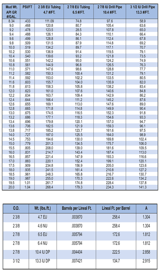
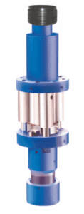
In low fluid level wells, any fluids placed in the tubing after the setting ball has reached its seat, will tend to shear the cylinder downward on the HM Bridge Plug. Chart #1 shows the pressure created in psi per barrel of fluid added, and Chart #2 shows the feet of fill-up per barrel of fluid added. Since 2010 psi pressure in favor of the tubing at the tool is required to initiate the setting sequence, we suggest the following method for calculating the required applied pump pressure.
- Determine fluid weight in pounds per gallon (#/gal) or psi per foot (psi/ft)
- Estimate fluid level from surface of well. NOTE: The tubing string will fill during running in through the fluid fill ports
- From Chart #1, select the appropriate column for the size of tubing string and line for appropriate fluid weight
- From Chart #2, select the appropriate column for the size of tubing string and determine the lineal feet per barrel of fluid
- Multiply the depth of fluid level from surface by the lineal feet per barrel from Chart #2 to determine the required amount of barrels of fluid to fill the tubing string
- Multiply the barrels required to fill the tubing string by the psi barrel figure from Chart #1. This figure will give you the total hydrostatic head exerted by the fluid in the tubing string when completely filled. If this figure is less than the required 2010 psi, sufficient pump pressure must be added to achieve the 2010 psi required pressure. In those cases where the calculated pressure for the fluid to fill the tubing string exceeds the required 2010 psi, you need only to add or fill with the necessary barrels of fluid to achieve the required 2010 psi This may be calculated by dividing 2010 psi by the psi. per barrel figure from Chart #1. Over pressuring cannot occur since the tool will be activated at 2010 psi and the downward travel of the cylinder will vent the excess fluid into the annulus above the plug before damage occurs. Once the required pressure is created at the plug, sufficient tension must be applied as shown in step #4 under setting H-M plug. Complete setting sequence as described in step #5
To Calculate Stretch To Set: S = ( F x L x 12 ) / ( E x A ) = Elongation due to tension (inches)
F = Tension pulled over normal weight (pounds) L = Length of running-in string (feet)
E = 30,010,010 = Modulas of elasticity for steel A = Cross-sectional area of running-in string (square inches)


